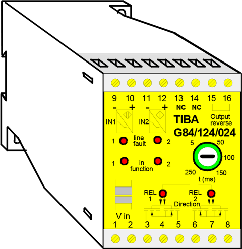
Railway Direction Detection | G84-96 Specifications Sheet 2008

Direction Detection
for inductive sensor NAMURType G84/124/... with MOS relay
Type G84/120/... with optocoupler
Type G84/96/... with relay
- Signal input by inductive sensor NAMUR
- Output either with relay contact or semiconductor MOS relay.
- Line fault monitoring for the connected switch
- Function reversal by jumper possible
The direction detection system analyzes 2 overlapping pulses with a phase shift of 90° and switches the output relay according to the direction of movement by the passing wheel flange over the signal transmitter (wheel sensor).
Operating principleThe complete direction detection system consists of 2 signal transmitters and the direction detection unit. As signal transmitters, the following wheel sensor models can be used:
- 2N59-1R-200-45 Double wheel sensor according to DIN 19234 (NAMUR)
- 2N59-1R-200-40 Double wheel sensor according to DIN 19234 (NAMUR)
All signal transmitter conductors are monitored for line fault. The transmitters (wheel sensor) operate contactless, i.e. there is no mechanical link between the wheel flange (trigger element) and the wheel sensor (signal transmitter). When a ferromagnetic material such as the wheel flange moves along the active switching surfaces of the wheel sensor (signal transmitters), the wheel sensor generates an electric pulse which is fed to the direction detection unit. The 2 input pulses need to be shifted by 90° one with respect to the other and need to overlap by 90°.
This pulse sequence is analyzed by the direction detection unit and made available as an output in the form of a contact pulse. These output pulses can be set to a duration length of 5 to 250 ms.
Specifications
| input frequency: | ≤ 500 Hz |
|---|---|
| emperaturr range: | -25° C to +60° C |
| Operating voltage: | 230 VAC, 115 VAC 48...60Hz, 12VDC or 24VDC ±15%, 3.5 VA, 2.5W |
| Protection class: | Casing IP 40, class IP 20 |
| Casing material: | Polycarbonate/ABS |
| Installation: | On base plate or top hat rail DIN 50022 |
| Dimensions: | L 75 x W 55 x H 110 mm |
| Weight: | AC version 350 g DC version 250 g |
| Terminal cross-section: | 4 mm² |
Input circuit:
| 2 NAMUR inputs | according to DIN 19234 |
|---|---|
| Voltage: | 8.2 VDC |
| Internal resistance: | 2.5 KΩ |
| Switching threshold: | 1.55 V |
| Switching hysteresis: | 0.2 V |
| Line fault monitoring: | Display via LED and output on 1 |
Output circuit:
| Delay: | 5...250 ms |
|---|---|
| Photo MOS Relay | 150 V AC/DC, 100mA |
| Resistance R on | 8 Ω |
| Relay Contact rating: | 300 VDC / 250 VAC, 8 A 50 W / 2000 AV |
| Optocoupler rating Voltage: | 80 V DC |
| Current: | 100 mA |
| Voltage drop: | ≤ 1.5 V at maximum current |
| Delay: | 5 to 270 ms |

