Axle Counting Technology

axle_counter
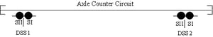
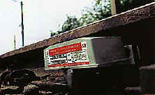
The Pintsch Tiefenbach axle counting system (TAZ) was developed in connection with the proven electronic double wheel sensor (DSS) for issuing clear and occupied notifications on station track sections, point switch zones, line sections and other track clear-occupancy applications.
This provides users in the railway sector, such as Mainline, Shortline, Industrial railways, or suppliers of complete railway safety systems with reliable, safe and low-cost train position detection and clear notification technology.


Applications:

  • Line-clear notification for station track sections, points switch zone protection, bridge section protection, line section protection, and approach or island circuit overlays.  
  • Decentralized points-clear notification for electrical locally-set points with switching protection and automatic switching from the trailing side.  
  • Occupied/Cleared notification for automatic train operated grade crossing protection systems.

axcntsym

axle_circuit

By deliberately using tried and tested components from the Pintsch Tiefenbach range of railway technology products, many operational and technical advantages have been secured for the user which make the use of this technology attractive even in areas with simple operational setups, in hump yards and gravity shunting systems, on single-track or multi-track mainline or regional lines as well as on tram and city railway systems offering local public transport.

dmir_bridge


wsensors

Double wheel sensor (DSS):
Type Application
2N59-1R-200-45 for speeds up to 37 mph
2N59-1R-200-40 for speeds up to 220 mph
2N59-1R-400RE-40 for speeds up to 220 mph with off rail detection
2N59-1-200-47 for tram wheel sets and speeds up to 44 mph

1. Maintenance-free sensor technology (double wheel sensor), unaffected by all known sources of interference (e.g. traction reverse currents, rail braking, radio-frequencies etc).

2. No electronic evaluation systems required near the track.

3. System functions irrespective of ballast parameters, the state of the superstructure, axle shunting and weather conditions.

4. Secure detection of all standard wheel-set types, even for low-floor vehicles.

5. Modular construction using Euro plug-in boards therefore allowing easy expansion and low-cost assembly of complete clear notification systems with multiple use of components.

6. Decentralized, low-cost installation of control systems in exterior boxes (without climate control!) is possible, e.g. for decentralized point switch controlling and block systems in the public transport sector, station control systems for regional traffic, for grade-crossing safety systems, or island and approach overlay circuits.

Axle Counting Theory

Axle counting systems provide detection of track vacancy through the process of counting wheel flanges as they pass over wheel sensors. A simple axle counting circuit consists of two double wheel sensors, which define the boundaries, or limits of a protected zone of track. Wheel flanges entering this protected zone or “virtual track circuit” are counted in at the entry sensor and counted out at the exit sensor. When one or more axles are present in the axle counting circuit, that zone, or section of track is determined to be occupied in the same manner that the presence of an axle atop a traditional track circuit shunts the track. When the number of axles (wheel flanges) present in the circuit restores to zero,the protected zone is determined to be vacant.

For an axle counting system to function as a virtual track circuit, it is necessary to delimit the axle counting circuit using double wheel sensors. This allows the sensors and associated evaluation equipment to determine direction of movement into, or out of, the circuit, thereby incrementing a counter or decrementing a counter, which in turn controls a suitable relay release module or other ancillary equipment interfaced with a signal system or highway grade crossing signal system.

axcntsym

The graphic above represents a wheel flange moving from left to right over a double wheel sensormounted on the gauge side of a rail. In the example above, because the wheel flange is detected atsensor one (S1) first, followed by sensor two (SII), we know the direction of movement is from left to right in the diagram. The associated evaluation equipment, which interfaces and controls the railroad signals, provides the following basic functions:

1. The evaluation equipment, via a switching amplifier module, excites the electromagnetic field needed to detect the passing wheel flange. This field interacts with the head of the rail and is damped by the passing wheel flange, resulting in an analog impulse.

2. The evaluation equipment detects the change in voltage drop across the sensor pair, performs interference pulse suppression and then analog-to-digital conversion. This information is sent to a counter module, which can be either a firmware or software device, and, in some cases, also to relay-release module.

3. The counter is then incremented or decremented to determine track occupancy or vacancy.There are obviously many nuances to the above process, which are too complex to cover in detail here.Suffice to say, the above process incorporates a variety of fail-safe and redundant process to ensure the highest level of safety. As a matter of fact, Pintsch signal systems have never experienced a reported activation failure, despite a quarter century of service on North American freight and transit railroads.

The Wheel Sensor

The heart of any axle counting system is the wheel sensor. While the idea of designing a wheel sensor sounds easy to the uninitiated, it is, in fact, a complex problem in the field of applied physics. Consider these factors:
  • The wheel sensor must respond consistently to passing wheel flanges under a wide temperature range from sub-zero arctic conditions to triple-digit tropical temperatures.
  • The wheel sensor must respond consistently to passing wheel flanges when it is covered in ice and snow, immersed under storm water, or surrounded by industrial byproducts ranging from dirt and aggregates to ferrous taconite pellets.
  • The inductive characteristics must remain consistent over years despite exposure to moisture and corrosive contaminants in the nearby environment.

Pintsch wheel sensors are the product of decades of research and development, and manufacturing excellence. This ensures that our axle counting systems perform reliably under all environmental conditions.

axcntsym
A double track crossing approach at a steel-deck bridge. Blue fail-safe double wheel sensor in the foreground.

Vitality (Safety)

Vitality, or fail-safe principles are at the heart of the railroad signal and communications field. Our axle counting systems offer multiple layers redundancy and they incorporate carefully designed fail-safe functions. It is for this reason that the fastest rail networks in the world utilize our technology. As with other railroad signaling technologies, our axle counting systems are designed to revert to the most restrictive condition under any fail-safe condition, some examples of which include, but are not necessarily limited to:
  • When a sensor is displaced from the rail.
  • When a sensor within a double wheel sensor fails.
  • When a short or open occurs in the sensor cable.
  • When a major change in electrical characteristics of a sensor circuit occurs.
  • When an error in the axle counting process is detected in either the counting process or relay functions.

In fact, the level of redundancy, the back-checking processes, and the anti-valent features within our axle counting systems provide a level of redundancy not found in many commonly used railroad signal products of other manufacture.

While all of the details are too extensive to cover in a brief discussion, suffice to say that one may not find the level of safety and redundancy offered by Pintsch on your next commercial airline trip!

Complexity

Pintsch axle counting systems can handle any type of track layout, any type of train movement or switching process, and any speed of operation. On-track equipment can enter or exit axle counting circuits from any direction. On-track equipment can be switched through an axle counting circuit in multiple directions and the system will always resolve properly. Any type of railroad signaling application can be managed efficiently through axle counting. Some examples include:
  • Island circuits.
  • Trap circuits.
  • Approach-Island-Approach grade crossing circuits.
  • Complex interlocking systems.
  • Switch control, protection and yard control functions.
  • Speed measurement.
  • Red-light overrun and similar PTC functions.
  • Industrial process controls
  • ….and more.

A few system examples:

axcntsym
A typical approach-island-approach system
axcntsym
An interlocking system in Minnesota built on axle counting principles.
axcntsym
A complex crossing system in Michigan
axcntsym
A solar powered crossing powering an axle counting grade crossing system in New Jersey.