Pintsch MC6 Switch Protection System
The MC6 axle counting system utilizes double wheel sensors in combination with the electronic evaluation components to form an incredibly versatile, safe and reliable train detection and evaluation system. Output to higher-level signaling layers such as a processor network or control circuit, is done by relay outputs.
Applications
- Train detection within yard and industrial single track sections
- Switch protection within hump yard, classification yards and industrial facilities


- Train operated, direction-dependent strike in via double wheel sensors (DSS) at the entrance to each protected zone switching on independent of speed
- Linear track clearing notification implemented by an axle counter circuit using up to 4 (DSS) wheel sensors
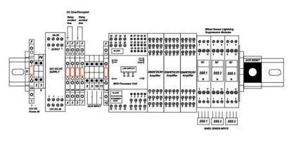
- The MC6 Unit: consists of four components, 2 MC6 Axle Counting Units, MC6 Communication Unit and MC6 Display Unit.
- The MC6 Axle Counting Unit (MC6AC) is responsible for the actual axle counting and all the other safety related activities.
- The MC6 Communication Unit (MC6COM) is mainly responsible for the communication between user and MC6 axle counting system through Telnet, USB, serial cable and web browser. It is also the storage medium for configuration files and log files.
- The MC6 Display Unit controls the LEDs and shows the actual information on 7-segment display
- The MC6COM represents an interface, through which the user can configure the MC6 axle counting system and manipulate the files that are stored in internal Flash or a USB flash drive.
- G94 module: Supports the processing and filtering of the sensor signals (1 double wheel sensor) and communicates the pulse and error information to the MC6 processors FEM inputs
- Fail-safe design
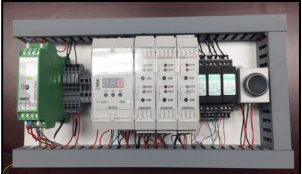
- Modular compact DIN-Rail hardware and software architecture with relay interface to the external circuit/control system
- Extensive integration results in a compact cost effective track vacany detection solution
- The sensor technology (double wheel sensor / axle counting) is maintenance free and unaffected by all known sources of interference (e.g. traction reverse currents, rail braking, etc.)
- Axle counting system continues to function independent of ballast conditions,the state of the superstructure, weather related conditions or electro-magnetic interferences
- Integrated real time event and diagnostic data logging designed for optimum maintenance support
- Intuitive Web interface for system configuration, diagnostic information and live real-time circuit monitoring
- The axle counting system is designed for low cost installation in exterior control boxes
- The axle counting technique for clearing notification ensures high availability since push-pull shunting, vehicle stop or change of direction will not lead to operational hindrances.
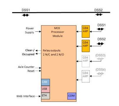
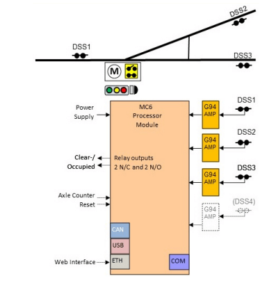
Block circuit diagrams:

Example 1: Configuration for train detection within a single track section

Example 2: Configuration for single switch zone protection using 3 DSS
When an axle or axles enter the circuit across one of the double wheel sensors the axle counting system will switch to the occupied state. The system remains in the occupied state until all axles are counted back out of the circuit (to zero) and then the system will switch back to the clear state. The contact lines serve as the interface to provide the occupancy detection information to the external control circuit.

