
Rail Wheel Sensor 2N59-1R-250-xx on New PINTSCH interface modules
Usage

In case the wheel sensor 2N59-1R-250-45 is operated on PINTSCH interface modules and no old technology is involved (4AB10/1105 and 4AB10/1105/1), the wheel sensor must be set to constant current. If third-party switching amplifiers are used which do not supply constant current, or if the modules 4AB10/1105 or 4AB10/1105/1 are used, the wheel sensor must be set to NAMUR.
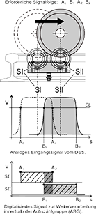
llustration 1: Switch principle of the wheel sensor
The purpose of a wheel sensor is the direction-dependent detection of the wheel flanges of track wheels. The metal of the wheel flange of a railway wheel rolling across the wheel sensor causes damping of the two individual systems.
This leads to a change in the internal resistance of the sensor systems and is evaluated in a subsequent interface module (ABG).
The arrangement of the two sensor systems is selected in such a way that the pulses generated by the damping overlap and can thus be used for direction-dependent axle counting and / or for direction-dependent switching commands (see illustration 1).